A-149-3 is the third module of the A-149-x range. In this group we present several functions of Don Buchla's "Source of Uncertainty 265/266" (SOU) modules that cannot be realized with existing A-100 modules. Some functions of Buchla's 265 and 266 SOU can be realized with existing A-100 modules.
Module A-149-3 is based on the homonymous "Fluctuating Random Voltages" by Buchla. Compared to the historic original a lot of functions have been added. For example the user has access to virtually all internal signals (e.g. Noisy Triangle or S&H) and there are a lot of adjustable parameters which were fixed in the original. For example the frequency and noisiness of the internal triangle oscillator, the correlation of the S&H and manual or automatic frequency control of the S&H clock oscillator. The fixed internal connections of the original are wired to sockets in the A-149-3 and can be used also individually as the connections of the original are realized as normalled sockets. That way e.g. the S&H or slew unit can be used independent from the other units.
The functions in detail:
As in the original a digital noise signal is filtered in three different ways. The three "noise flavours" are available at three sockets and can be used for all kind of noise applications:
- +3db (+3dB per octave, a bright noise, also called blue noise)
- -3dB (-3dB per octave, a dark noise, also called red or brown noise, Allan Strange calls it "reciprocal white noise")
- Flat (flat spectrum, also called pink noise)
In the original the -3dB output is used add some noise to an internal triangle oscillator with fixed frequency (~ 100 Hz) and fixed "noisiness". The result is called "noisy triangle". In the A-149-3 the frequency of the triangle oscillator and the level of the noisiness can be adjusted. The frequency is adusted by means of the Frq. control and the Range switch (~ 110Hz ... 5 seconds period in position high). In addition one can select between the -3dB and Flat output as noisiness source by means of an internal jumper. When Noisiness control is fully CCW one obtains a clean undisturbed triangle signal. With Noisiness control fully CW the result is a triangle signal with a lot of noise or randomness. The noisy triangle signal is available at the socket "N Tri" and is displayed with a dual color LED.
The "N Tri" signal is normalled to the signal input of the subsequent Sample&Hold unit (S&H). The clock signal for the S&H is generated by an internal rectangle oscillator. This signal is normalled to the S&H clock socket and is displayed by an LED. One can select between manual and automatic control of the clock period by means of a toggle switch. In position "man." the period is controlled manually by the "Period" control. With control "Period" fully CCW one obtains the shortest period or highest frequency. Turning the control up increases the period or lowers the frequency. In position "auto" of the switch the period is controlled by the slew unit. In this position a vactrol is used to define the frequency of the S&H clock. This vactrol is controlled in the same way as the vactrols of the slew unit, i.e. the period of the S&H clock changes simultaneously with the slew time. In the historic original only the auto mode was available. There was no manual control available.
The S&H has another special feature: the Correllation control. It's a feedback function where shares of the S&H output are fed back to the S&H signal input and mixed with the actual S&H input signal. The result is slurring the signal like a sub-audio lowpass filter, kind of a "digital slew function" because the gradation of the signal persists.
The S&H output is availabe at the corresponding socket and is displayed with a dual color LED.
The S&H output is normalled to the signal input of the subsequent Slew Limiter unit (SL). The core of the slew limiter are two vactrols (vactrol = combination of a light emitting diode/LED and a light dependent resistor/LDR built into lightproof case). The brightness of the vactrol LEDs can be controlled manually (control "Man." of the slew unit) and by an external control voltage (socket "SL CV" with associated attenuator "CV" of the slew unit). The brightness of the vactrol LEDs is displayed at the top of the front planel. As already mentioned a third vactrol can be used to control the frequency of the S&H clock oscillator simultaneously to the slew limiter. The SL output is availabe at the corresponding socket and is displayed with a dual color LED.
Due to the access facilities to many of the internal signals and connections it's possible to use the sub-units also for other applications. E.g. the noisy triangle signal, the S&H unit (incl. correlation) or the SL unit can be used for other signals. The S&H clock can be applied also from outside to synchronize the S&H to other signals. If required the internal clock signal is available at a pin header of the pc board.
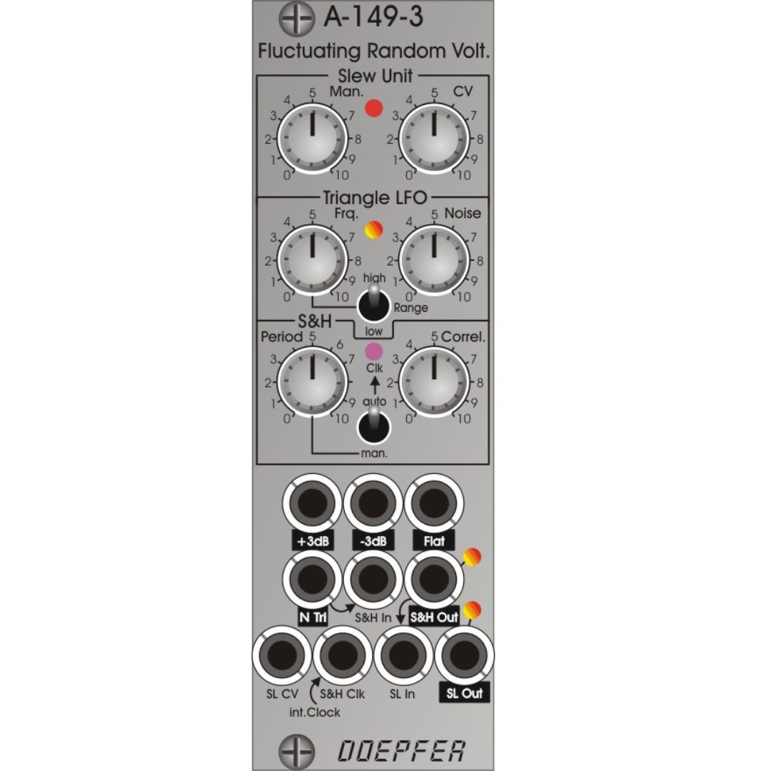
Controls, Switches and Displays:
- Slew Unit
- Man.: manual adjustment of the slew time
- CV: attenuator for the SL CV input
- LED: display of the slew function (bright = short slew lime, dark = long slew time), identical to the brightmess of the vactrol LEDs
- Triangle LFO
- Frq.: LFO frequency, range ~ 110 Hz ... 5 seconds period
- Noise: adjustment of noisiness (= perturbance of the triangle signal)
- +3dB/-3dB: switch for the source of noisiness
- LED: display of the noisy triangle signal, dual color LED (rot = positive / yellow = negative output voltage)
- Sample&Hold (S&H)
- Period: period of the internal clock signal for the S&H unit, fully CCW = shortest period or highest frequency, fully CW = longest period or lowest frequency
- LED: display of the internal clock signal
- Correl.: adjustment of the correllation of the S&H unit
- Man./Auto: switching between manual and automatic control of the clock frequency, when auto is selected the clock frequency is controlled by the slew unit
- LED: display of S&H output, dual color LED (rot = positive / yellow = negative output voltage)
- Slew Limiter (SL)
- LED: display of SK output, dual color LED (rot = positive / yellow = negative output voltage)
Sockets:
- +3dB : filtered digital noise with +3dB per octave (output)
- -3dB : filtered digital noise with -3dB per octave (output)
- Flat : flat noise output
- N Tri : Noisy Triangle output, about 10Vpp (-5V ... +5V)
- S&H In: S&H signal input, normalled to N Tri
- S&H Out : S&H signal output
- SL CV: control voltage of the slew limiter unit, connected to the corresponding attenuator "CV" of the slew unit
- S&H Clk: clock input of the S&H unit, normalled to the internal clock oscillator
- SL In: slew limiter input, normalled to S&H Out
- SL Out : slew limiter output
The arrow symbols indicate the normalling of sockets. Outputs are inverse labelled.
Technical details:
- Frequency range of the triangle LFO: about 110 Hz ... 5 seconds period
- Output level of the triangle LFO: ~ 10 Vss (-5 V...+5 V)
- Frequency range of the internal clock oscillator: about 3 seconds ... 30Hz
- Output level of the internal clock oscillator: ~ 10 Vss (0 V...+10 V)
- Required input level of the S&H clock input: +5V