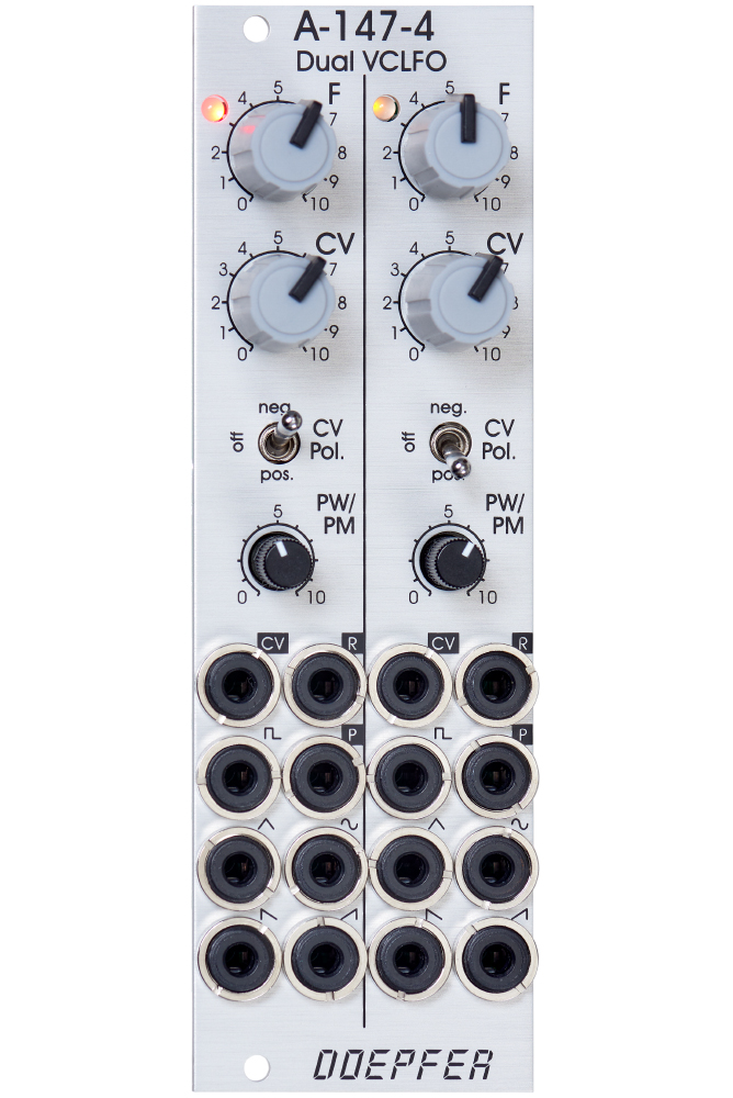
Module A-147-4 is a dual voltage controlled LFO (Low Frequency Oscillator). Each LFO has the five waveforms triangle, sine, rising and falling sawtooth, as well as rectangle available. The rectangle output features manually adjustable pulsewidth and pulsewidth modulation by means of an external control voltage. The core waveform is triangle. The other waveforms are derived from triangle by means of waveform converters. The frequency of each LFO can be adjusted manually and modulated by means of an external control voltage with associated attenuator and polarity switch. By means of a jumper the basic frequency range of each LFO can selected: about 0.02 Hz (~ 50 seconds) ... 2.5kHz or about 0.0017 Hz(~ 600 seconds) ... 220Hz. That way each LFO can be used also as a VCO with a max. frequency of about 2.5kHz. Each LFO features a reset input which can be used to reset the triangle signal.
The module has these controls and in/outputs available:
- Control F : manual control of the frequency, for each LFO the frequency range can be selected by means of a jumper from two values (see technical notes)
- frequency coverage of control F in the high frequency range: about 0.075 Hz (~ 13 seconds) ... 1,4kHz
- frequency coverage of control F in the low frequency range: about 0.007 Hz (~ 140 seconds) ... 125Hz
- Control CV: attenuator for the signal applied to the CV socket, by means of a jumper a small positive voltage can be applied to the switching contact of the /CV/ socket, as long as no patch cable is connected to /CV/ socket the CV control then works as fine control for the frequency
- Switch CV Pol.: polarity switch for the signal applied to the socket /CV/
- Control PW/PM: combined control for manual and CV control of the rectangle pulsewidth:
- when no patch cable is connected to socket /P/ the control is used to adjust the pulsewidth (PW) manually
- when a patch cable is connected to socket /P/ the control works as attenuator for the external CV signal with a basic pulsewidth of 50:50.
- Socket /CV/: frequency control voltage input, in the factory the module is adjusted so that the sensitivity of this input is exactly 1V/octave when the CV control is fully CW.
- Socket /R/: reset input, according to the associated jumper the reset input is edge triggered or level controlled (see technical notes for details)
- Socket /P/: pulsewidth control voltage input
- Sockets with waveform symbol: output of the waveform in question (triangle, sine, rising and falling sawtooth, rectangle)
- The output voltage ranges are about -5V ... +5V (10Vpp), except the rectangle output
- For the rectangle output one can choose by means of a jumper if the range is about -5V ... +5V or 0...+10V.
- LED: visual control of the LFO (triangle)
- The inputs of the module are labelled with white characters on black background (in the text included into two slashes). The outputs are labelled with black characters.
Technical notes and special features:
- The basic frequency range of each LFO can be selected by means of a jumper. The settings correspond to two different capacitor values for the VCO circuit. The relation between the two ranges is about 1:11. When the upper range is selected frequencies from about 0.02 Hz up to 2.5kHz can be generated. For the lower range the values are about 0.0017 Hz ... 220Hz. To obtain these full frequency ranges external control voltages are required. With the frequency control F only the frequencies mentioned above are possible.
- Apart from that the range for the manual control F can be reduced to obtain a finer resolutuion. For this a jumper has to be removed. The range of control F is then reduced to about 1:4.5 only.
- In the factory the starting voltage of the triangle output after a reset is adjusted to 0V, i.e. the triangle starts from 0V with the rising slope after a reset. By means of a trimming potentiometer the starting voltage can be adjusted to another value (e.g. to -5V).
- Another jumper is used to set the reset behaviour to edge triggered or level controlled. When set to edge triggered the rising edge of reset signal is used for the reset (independent of the duration of the "high" state of the reset signal). When set to level controlled the triangle output remains at the starting voltage as long as the reset signal is "high". Only when the reset signal turns "low" the triangle starts.