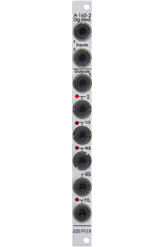
Module A-165-2 includes six modification circuits for digital signals (clock, gate, trigger, start, stop etc.) which are derived from the two input signals Input 1 und 2:
- inverted signal of Input 1 (labelled 1)
- inverted signal of Input 2 (labelled 2)
- T flipflop (toggle flipflop), controlled by Input 1, this output changes it's state whenever a the rising edge of Input 1 appears (labelled 1/2, as it works similar to a 1:2 frequency divider)
- Set/Reset flipflop, this output changes it's state to "high" during the rising edge of Input 1 and turns "low" during the rising edge of Input 2 (labelled RS)
- inverted output of the Set/Reset flipflop (labelled RS)
- pulse output, during both the rising and falling edge of Input 1 a short trigger pulse with about 50 ms lenght is generated (labelled with the sign ± and a rectangle pulse symbol)
The outputs 2, 1/2, RS and the pulse output are equipped with LEDs that display the state of the output in question.
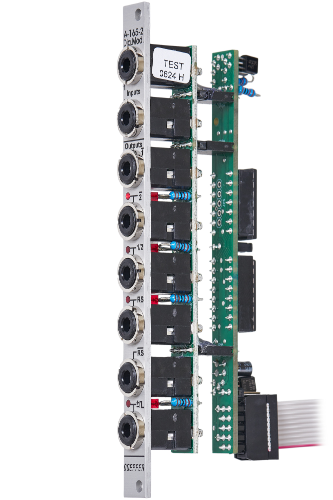
The output level for all six outputs can be set to 0/+5V or 0/+11V by means of a jumper on the pc board.
Voltage thresholds for the input voltages:
- voltages below +0,8 V are treated as "low"
- voltages above +3 V are treated as "high"
Typical applications
- starting and/or stopping of events or switching operations with the RS or RS output (e.g. controlled by the trigger outputs of a sequencer, e.g. in combination with electronic switches)
- generation of inverted digital signals
- frequency division (1/2 output)
- generation of short pulses during the rising and falling edge of a digital signal (e.g. triggering an envelope at both rising and falling edge of a gate signal).